So, it’s been almost 3 months since the last post on Datalogger, and a lot of progress has been made in that time. The main highlights: FAT32 file system is in a working state with file write speeds at around 600kByte/s, which exceeds our requirements. With some more optimizations, we hope to push this number closer to 800kByte/s, possible allowing for more data (perhaps cockpit audio?) to be recorded. Additionally, we plan to release everything (circuit schematics, board layout, and all code) as open source under the terms of the three-clause BSD license when it’s ready.
While all this is great news, it certainly doesn’t make for a very interesting post. So, if you’re interested in how we accomplished those fast write speeds on a general-purpose microcontroller, keep reading!
A quick refresher on the Datalogger System.
What does Datalogger do? It logs data, just like the name implies! On our solar car, it records every CAN message transmitted and stores it to an SD card for later analysis. While this sounds like an easy task, it really isn’t. On a PC, this would require only several lines of code since the details of file access is abstracted away and performance isn’t a concern given the powerful hardware. However, on a microcontroller platform like we’re using, you really have to code from scratch (including implementing SD card drivers and a file system layer) and seriously optimize performance just to be able to keep up with the data it receives.
In our last post, we used techniques like software pipelining (loading the next byte of data to be transmitted to the SD card while the current one is being transferred), manual inlining (to avoid a function call overhead), and using the multiple block write command to increase raw write performance to near 1 MByte/s. However, there were still problems – for pipelined operations, received data had to be read before the next byte arrived which created strict timing constraints. And more importantly, communications with the SD card tie up the processor leaving it unable to do anything else. So even though we achieved high data rates (throughput), we still might not be able to check the received CAN data often enough (latency) and consequently lose data. Not good for something that is supposed to record everything.
So, how much do SD card communications cost?
In most (if not all) SD cards, read and write operations must occur in blocks of 512 bytes. On our microcontroller, the SPI module which communicates with the SD card has a maximum speed of 10 MHz while the processor runs at 20 MHz. Since SPI shifts out one bit at a time, each block takes up to 512 bytes * 8 bits/byte * 2 processor cycles / bit = 8192 processor cycles, and that doesn’t even take account the time waiting for the card to complete the operation. That’s certainly not very efficient – now if only there was some way to move these boring data transfer operations into the background…
Enter DMA.

DMA – meaning Direct Memory Access – is a hardware feature allowing memory-to-peripheral transfers to occur independent of the processor. Essentially, code that involved repeatedly waiting for transmissions to complete before sending the next byte can now be reduced to loading a pointer to the beginning of the data, loading the length of the data, and requesting a DMA transfer. Afterwards, the DMA module continues the block transfer in the background while the processor is free to do other tasks.
It turns out that this works quite well with SD cards – data is transferred in blocks of 512 bytes, and the time to initiate a DMA transfer is tiny compared with the time to transfer that much data. So there is definitely a performance gain in switching to DMA.
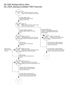
The code, however, is much more complicated. The once clean, sequential code which dealt with the SD card write protocol now has to be broken into chunks to handle the different write stages – from sending the data block to waiting for a data response to waiting for the busy signals to end. Additionally, interrupts are necessary to maximize performance, but can also cause race conditions if not done carefully.
To deal with this mess, we structured the DMA code around a state machine, and created detailed flow charts about what happens where. As for the race conditions, we specified who (either user code or interrupt handler) should have control of the shared variables. So far, this has worked pretty well and the code has performed flawlessly.
To keep data flowing to the SD card, we also implemented a double buffering scheme. The size of each buffer is equal to the size of a SD card block, and the concept is that while one buffer is being filled by the processor with data, the other buffer can be transferred to the SD card concurrently in the background. However, two blocks worth of data might not be enough to deal with large data bursts, so we also added a third larger, but non-DMA capable, overflow buffer. The primary reason for this (as opposed to just increasing the number of block-size DMA buffers) is because of the limit on DMA RAM space on our microcontroller.
As for results, we’ve been able to get up to 900kByte/s when writing a large amount of data. And since we used DMA, most of the write operation happens in the background allowing the processor to work on less boring tasks such as actually generating the data to be written.
File System Layer: FAT32
It would be great if we were done there, but then the user experience would be terrible: to read the stored data, you would need to install a disk editor on your computer to do raw sector reads. It would be much better if the data could be stored in a file. Of course, this requires yet another layer of complexity: implementing file system code.
The file system basically keeps track of where files are on the disk. We chose FAT32 since it is the most common one for small external storage devices and isn’t terribly difficult in concept. As a brief overview, a FAT32 partition mainly consists of three parts: filesystem information (which is pretty self-explanatory), the file allocation table, and the cluster area. The file data itself is broken down into fixed-length (typically 4 kBytes) clusters and stored in the cluster area. These clusters are structured as a liked list – that is, for each cluster there is a pointer to the next cluster in the file, and this list of pointers are stored in the file allocation table.
What all this means for us is that now we have overhead – instead of just writing data to disk, we need to update the filesystem information too.
One simple approach to writes would be to just write file data and allocate clusters as needed. However, whenever we allocate clusters, we need to perform writes in 3 different locations on disk to keep the filesystem consistent, and this random-access pattern is expensive compared to writing data sequentially. Therefore, it would make sense to allocate clusters as rarely as possible.
One optimization around that is to pre-allocate the entire file. This operation takes advantage of the fact that cluster pointers are stored sequentially, allowing a large amount of clusters to be allocated at once. However, this is inadequate for our needs, as we don’t know what size our file will be nor do we want a excessively long start-up delay.
So, we compromise. Instead of pre-allocating the whole file, we write one block’s (512 bytes, for SD cards) worth of cluster pointers at a time, allocating 128 clusters or 512 kBytes of space. This both reduces the frequency of overhead write operations and maximizes the use of the block of cluster pointer data written. However, file sizes rarely lie on exact 512 kByte boundaries, so when the user application signals that there is no more file data and the file is to be closed, we go back and do a cleanup operation, deallocating extra clusters and writing the precise values for the final file system data.
We implemented many other optimizations as well, and most of these fall under the concept of a time-memory tradeoff as caching techniques. The idea is that communication with the SD card is expensive (even with DMA – unnecessary operations can still be replaced with useful data transfers), so any data that needs to be used periodically is stored in the microcontroller memory instead of being re-read from from disk. This creates a significant memory requirement (several kBytes), but almost halves the number of overhead SD card operations.
As you’ve seen at the beginning, these optimizations combined give us a FAT32 file write speed of around 600 kByte/s, and that’s just with the implementation of the big concepts rather than sleek optimized code. If you’re interested in the test conditions, see the appendix at the end.
Library Release
So, when we have a releasable implementation complete, we plan to release the FAT32 library and datalogger application as open-source code under the 3-clause BSD license. The FAT32 code will mainly be optimized for sequential single file writes, but other operations are possible. Therefore, let me close this post with a question: if you’re interested in using this library, what features would you like to see?

Appendix: Test Conditions:
- Write operations use DMA with the aforementioned double DMA + overflow buffer scheme.
- Speed is the asymptotic upper bound – it does not include the file initialization operation or the termination operation. However, those operations combined take on the order of a hundred milliseconds and are insignificant for large files.
- The FAT32 File Write function (which buffers input data) is repeatedly called 8192 times on a 512-byte buffer for a total file size of 4 MBytes. Note that since the processor is much faster than SD card write operations, this benchmark result should also be valid if the file write function is repeatedly called on smaller chunks of data. Also note that this would involve several cluster allocations.
- Benchmark results include time to generate the data, which basically involves loading the buffer with a combination of a pre-set string and a generated integer. Note that this time is overlapped with SD card operations through DMA.
- The write total time came out to around 6 seconds. This was measured with a logic analyzer and is the time between the beginning of the first data byte to the end of busy signals after the last block transferred.

Dear All, Your datalogger application seems to be awesome as you have described above. In the end you mentioned that you have planned to release this FAT32 implementation as open source library. Can you please inform me that when will you release it.
Regards.
Hi Usman,
An open source release is still part of the roadmap, although there is no solid date. If I were to pull a time out of a hat, it would probably say sometime this summer, although the official word is still “when it’s ready.” We may, however, open up the SVN repository earlier when the code is in a clean enough state.